A recent spur of interest in indoor robotics has increased the importance of robust simultaneous localization and mapping algorithms in indoor scenarios. This robustness is typically provided by the use of multiple sensors which can correct each others’ deficiencies. In this vein, exteroceptive sensors, like cameras and LiDAR’s, employed for fusion are capable of correcting the drifts accumulated by wheel odometry or inertial measurement units (IMU’s). However, these exteroceptive sensors are deficient in highly structured environments and dynamic lighting conditions. This letter will present WiFi as a robust and straightforward sensing modality capable of circumventing these issues. Specifically, we make three contributions. First, we will understand the necessary features to be extracted from WiFi signals. Second, we characterize the quality of these mea surements. Third, we integrate these features with odometry into a state-of-art GraphSLAM backend. We present our results in a 25×30 m and 50×40 environment and robustly test the system by driving the robot a cumulative distance of over 1225 m in these two environments. We show an improvement of at least 6× compared odometry-only estimation and perform on par with one of the state-of-the-art Visual-based SLAM.
The following video gives a high-level idea on how the Wi-Fi bearing measurements are made. It also shows when the measurements are dropped to have robust measurements.
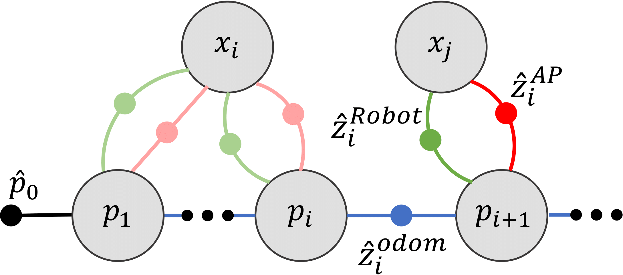
The robots movement over three timestamp are shown. Relative odometry is measured between two consecutive robot poses. At each timestamp, the robot ping’s an AP (orange arrow) and receives a pong reply (green arrow). For each ping and pon transmission the AP-sided and Robot-sided bearing of the signal is computed respectively. These measurements can then be fed into GTSAM for accurate drift correction and to recover the robot's trajectory.
Here we describe the environments and the datasets collected in these environments. We further showcase P2SLAM results as compared to camera-based baseline RTABMap. We find that in all datasets inclusion of WiFi-based sensing for localization performs on par with RTABMap and makes a strong case for the inclusion of these simple sensors within SLAM systems.
1. Env-1- Atkinson Hall 4th Floor -- 20 x 30 m (65 x 100 feet) standard office environment with complex mulitpath and mulitple Non-line of sight conditions. A total of 5 AP's were deployed in this environment and two paths ( Dataset 1 and Dataset 2 ) were taken as described below.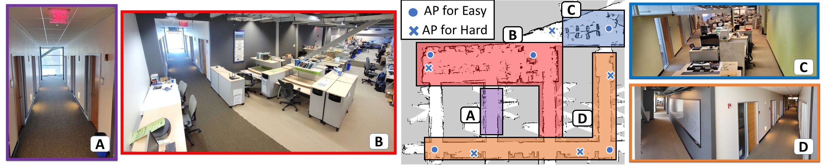 2. Env-2- Atkinson Hall Ground Floor -- 50 x 40 m large environment covering mulitple corridors and large lobbies and auditorium spaces. Dataset 3 was collected in this environment.
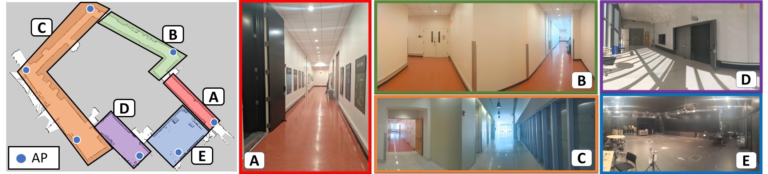
1. Env-1- Atkinson Hall 4th Floor -- 20 x 30 m (65 x 100 feet) standard office environment with complex mulitpath and mulitple Non-line of sight conditions. A total of 5 AP's were deployed in this environment and two paths ( Dataset 1 and Dataset 2 ) were taken as described below.
2. Env-2- Atkinson Hall Ground Floor -- 50 x 40 m large environment covering mulitple corridors and large lobbies and auditorium spaces. Dataset 3 was collected in this environment.
First, we summarize all our results in the following table. We show the median and 90th percentile translation and orientation errors in centimeters and degrees respectively. We show across three sensing modalities -- using odometry only, using odometry + Camera (RTABMap) and using odometry + WiFi (P2SLAM) -
Sensors | Env 1 - Dataset 1 | Env 1 - Dataset 2 | Env 2 - Dataset 3 | |||
|---|---|---|---|---|---|---|
| Trans (cm) | Orient (deg) | Trans (cm) | Orient (deg) | Trans (cm) | Orientation ( deg) | |
| Med (90th) | Med (90th) | Med (90th) | Med (90th) | Med (90th) | Med (90th) | |
| Dead reckoning | 180.6 (513.9) | 8.64 (18.1) | 378.6 (1156) | 23.35 (37) | 422 (1098) | 16 (30.5) |
| RTABMap | 36.8 (165.7) | 2.97 (10.83) | 38.5 (63.7) | 0.74 (2.69) | 61.5 (256) | 2.2 (7.99) |
| P2SLAM | 26.9 (54.7) | 1.28 (3.16) | 40.4 (76.9) | 1.32 (3.7) | 65.2 (158) | 1.65 (3.95) |
Next, we present in-depth analysis for the above three datasets. Further details to use this dataset is given below.
1. Env 1 - Dataset 1 (easy)- Simple robot movement where we traverse all the corridors, for a total path length of 330 m (approx) at 18 cm/s. AP's are placed in the locations marked by circles in the above figure. 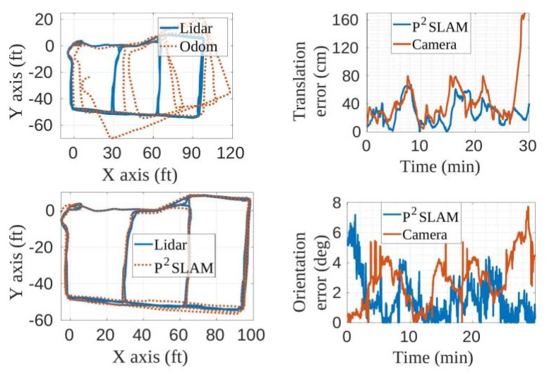
2. Env 1 - Dataset 2 (hard)- Complex robot movement where the robot traverses different nooks in the environment. This path closely replicate one taken by a vacuume cleaner or package delivery robot. Total path-length travelled is 495 m (approx) at 28 cm/s. AP's are placed in the locations marked by cross in the above figure. 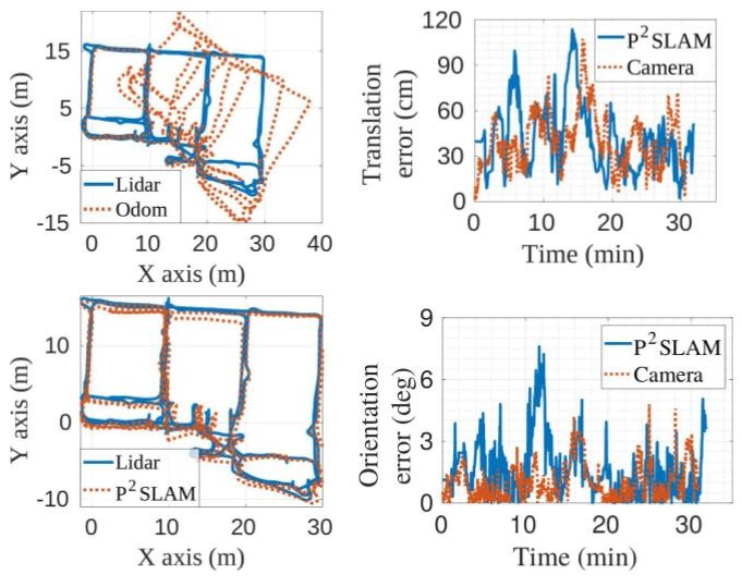
3. Env 2 - Dataset 3 - Simple robot movement where mulitple corridors are traversed at 28 cm/s for a total path length of 400 m (approx). 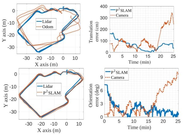
SWaP-C is a common industry acronym for Size, Weight, Power and Cost. In P2SLAM, we show the efficacy of WiFi-based sensing for robotic localization and navigation. Furthermore, we claim that the SWaP-C metrics for WiFi radios is 10 times better than LiDAR's. Here we further justify this claim.
From the above table, we can see that taking a conservative power estimate of the NodeMCU, we find the power consumption to be close to 1 W, which is about 8 times lower than the Velodyne Puck Lite.
Size
The smallest surround LIDAR, [Puck Lite](https://www.mapix.com/wp-content/uploads/2018/07/63-9286_Rev-H_Puck-LITE_Datasheet_Web.pdf) by Velodyne Lidar, has a very small form factor with a 3.5" diameter and height of 2.82". Developing a WiFi sensor using the [ESP8266 NodeMCU](https://www.nodemcu.com/index_en.html) with multi-antenna capability will have dimensions of (2" x 1" x 0.5"), with the size of an 4-element linear antenna array at 9.8" or a square antenna array at 6.25".Weight
The Puck Lite weighs at 590 g. An ESP8266-based design would weight a meagre 9 g.Power
| Device | Power Consumption | Notes | Sources |
|---|---|---|---|
| Hokoyo Lidar | 8.4 W | Single channel | Datasheet |
| Velodyne Puck | 8 W | 16 channel | Datasheet |
| ASUS RT-AC86U | Measured @ 6.5 W in lab | 802.11AC, 5 Ghz, 20/40/80 MHz, 4x4 | |
| Quantenna | Measured @ 3.2 W in lab | 802.11AC, 5 Ghz, 20/40/80 MHz, 4x4 | |
| Intel 5300 | 1.6 W Rx, 2.1 W Tx | 802.11n, 2.4 Ghz, 20 and 40 MHz, 3x3 | Power measurements by Halperin et al. |
| TP-Link TL-WDR4300 (Atheros CSI tool) | 4.6 W | IEEE 802.11n, 2.4 GHz, 20/40 MHz, 3x3 | Power consumption database |
| ESP 32, NodeMCU | 240 mW x 4 ~ 1 W | 802.11 b/g/n, 2.4 GHz, 20 MHz | Measurement by JeeLabs |
Cost
Publicly available information about the Velodyne Puck prices the it at $8000. A simple NodeMCU WiFi sensor would cost less than $20.
The CSI data is named as channels.mat and the rosbag is named as data.bag in the resepctive dataset folders. All the datasets can be downloaded here (size = 19.6 GB). To access the dataset, you will need to fill out a brief Google Form to agree to the terms of usage. Upon form completion an email will be sent out with the download instructions.
The MATLAB files (channels.mat) are stored using HDF5 file structure and contain the following variables-
- channels_cli- [ n_datapoints x n_frequency x n_ap x n_rx_ant X n_tx_ant] 5D complex channel matrix received at the WiFi access points deployed in the environment.
- channels_ap- [ n_datapoints x n_frequency x num_aps x n_rx_ant X n_tx_ant] 5D complex channel matrix received at the WiFi access point present on the robot.
- cli_rssi_synced- [ n_datapoints x n_rx_ant x n_ap ] Received signal strength matrix at the environment's WiFi access point.
- ap_rssi_synced- [ n_datapoints x n_rx_ant x n_ap ] Received signal strength matrix at the robot's WiFi access point.
- cli_hw_noise_synced- [ n_datapoints x n_ap ] Hardware noise floor measured at the Environment's AP's when signal is received from the robot.
- ap_hw_noise_synced- [ n_datapoints x n_ap ] Hardware noise floor measured at robot's WiFi AP with signal received from each of the environment's AP's.
- ap- [1 x n_ap] cell matrix. Each element corresponding to [ n_rx_ant x 2] antenna positions in the global coordinates.
- labels- [ n_datapoints x 3 ] 2D best-estimate ground truth XY labels + heading of the robot -- computed using Cartographer using onboard Lidar and internal odometry.
- labels_noise- [ n_datapoints x 3 ] 2D XY labels + heading of the robot computed using only robot's wheel encoder (highly erroneous measurements)
- labels_imu- [ n_datapoints x 3 ] 2D XY labels + heading of the robot computed using the robot's wheel encoder and internal gyroscope (less erroneous than only using wheel encoders)
- labels_vel- [ n_datapoints x 1 ] Velocity of the robot in m/s.
The rosbags (data.bag) contain the following topics-
- Camera Information from Intel Realsense D415. DS 1 uses the Orbbec Astra camera and its topics are in parentheses-
- /camera/color/camera_info (/camera/rgb/camera_info)
- /camera/color/image_raw/compressed (/camera/rgb/image_rect_color/compressed)
- /camera/depth_registered/image_raw/compressedDepth (/camera/depth_registered/image_raw/compressedDepth)
- Odometry Information from Turtlebot base-
- /mobile_base/sensors/core
- /mobile_base/sensors/imu_data
- /mobile_base/sensors/imu_data_raw
- /odom
- /tf
- Hokuoyo Lidar scan information-
- /scan